
SBB Be 4/7
| SBB Be 4/7 | |||||||||||||||||||||||||
|---|---|---|---|---|---|---|---|---|---|---|---|---|---|---|---|---|---|---|---|---|---|---|---|---|---|
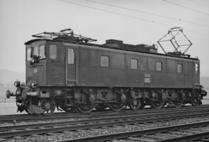 Be 4/7 12502 | |||||||||||||||||||||||||
| |||||||||||||||||||||||||
| |||||||||||||||||||||||||
| |||||||||||||||||||||||||
| |||||||||||||||||||||||||
The Be 4/7, nicknamed the Big Sécheron is an electric locomotive for use on the Gotthard line by the SBB. It represents an early experiment in electric locomotive design. In contrast to the other locomotives of the era, the Be 4/7 did not have rod drive, but individual electrically-driven axles mounted directly on bogies.
Background
[edit]When the second series of the Be 4/6 was ordered in July 1918, the SBB decided to order a new locomotive at the same time, which deviated in many ways from the other locomotive types.[1]: 59 [2]
The company Société anonyme des Ateliers de Sécheron (SAAS) offered a locomotive together with the Swiss Locomotive and Machine Works (SLM) that did not have a rod drive, but instead a motor for each driven axle. The proposed drive came from the Westinghouse company (USA) and licensed to SAAS for exclusive use in Switzerland. Applications, in particular with an output of over 500 kW per wheel set, had not yet been attempted. Nevertheless, a bid was submitted.[1]: 59
SBB asked for the fulfillment of the subsequent specification:[1]: 52
- Top speed 75 km/h
- Haul of 300 t trailer load on a 26 ‰ slope at 50 km/h
- Safe starting on a 26 ‰ slope and accelerating the same load to 50 km/h in 4 minutes
- three return journeys Lucerne-Chiasso within 24 hours (1,360 km)
- Electric brakes to slow the locomotive on downslopes
- Possibility of multiple unit control.
The award went to SAAS and SLM, and SBB took delivery of the units on October 18 1921 for operations between Bern and Thun.[2]
Technical
[edit]Mechanical
[edit]The running gear consisted of two powered bogies, on a separate chassis that was linked to the buffers and drawbars. The locomotive body rode on top of the chassis. Each bogie contained two driving axles and one running axle designed as a Bissel axle. The bogie on the front of the locomotive also had an internal running axle designed as an Adams axle. This additional axle, which gave the locomotive the asymmetrical wheel arrangement (1'B1')(B1'), was necessary due to a limit on the static axle load of 18.5 t in order to compensate for dynamic loads from the sprung single-axle drive. For adhesion reasons, the total weight of the locomotive was designed to be no less than that of a Be 4/6.[1]: 59
The traction motor housings of the twin or double motors (two motors in a common housing)[2] were supported on crossbeams in the bogies and bolted to supports. The torque of each double motor was transmitted via a pinion to a common large gearwheel. This was attached to a hollow shaft that was mounted in the common motor housing and enclosed the drive axle. This hollow shaft quill drive drove the drive wheels via pinions and coil springs. The drive wheels were dimensioned so that wheel tires of the steam locomotives A 3/5 901-938 of the former Gotthard Railway Company could be used. These locomotives were about to be retired.[1]: 59–60
The locomotive body consisted of a continuous bridge with bolted-on box sections without any extensions. The locomotive bridge rested on the two bogies at three points:[1]: 60
- Fixed pivot bearing between the two driving axles of bogie I.
- Pivot bearing with longitudinal play between the outer driving axle and the Bissel axle of bogie II.
- Spring-loaded roller support bearing above the inner coupling of bogie II.
Thus, tensile and compressive forces between the train and the drive axles were not absorbed by the locomotive body. The floor of the locomotive bridge was shaped like a box. The motors and driving wheels protruded into this. Access to the motors was ensured by covers from above and in the longitudinal walls. A cooling air duct extending the entire length of the engine room was bolted to the ceiling of the box.[1]: 60
The locomotive body contained all the electrical equipment. The transformer was located in the center of the box.[1]: 60
Electrical
[edit]Main Circuit
[edit]The high voltage from the overhead line was collected by two pantographs. From each pantograph, the current was fed via a separator and a lightning protection coil to the electropneumatically operated oil-filled main switch. From there, the current flowed to the transformer. The transformer oil was cooled by tube bundles attached to the transformer cover and immersed in the oil. Ventilation air flowed through the tube bundles. The lightning protection coils were later removed because experience proved them to be unnecessary.[1]: 60
The four twin motors were connected in parallel. They received traction current via a bank of two sets of nine electropneumatic individual switches (hop-start control). The transformer had eight taps ranging from 100V to 864V. The 28 speed steps were created by interconnecting the hoppers with an auxiliary transformer and three choke coils.[1]: 60
Each twin motor had a separate reversing switch. The two reversing switches on each bogie were each controlled by a common electro-pneumatic drive. The reversing switches had the positions "Forward," "Reverse," and "Electric Brake." Individual defective twin motors could be disconnected by locking them in the neutral position.[1]: 60
Auxiliary Systems
[edit]The locomotive was equipped with the following 220 V-operated auxiliary systems:[1]: 60
- A rotary compressor.
- Two fans. These directed the cooling air through louvers in the locomotive roof into the engine room, via the ventilation duct to the traction motors, through the oil cooling pipes in the transformer, and through the resistor shafts.
- A converter group for battery charging.
- Driver's cab heating and oil heating plates.
The train heating was originally supplied with voltages of 800V, 1,000V, and 1,200V via mutually interlocked transformer jumpers. Later, the voltages were changed to 600V, 800V, and 1,000V. At a later date, the 600V and 800V stages were added.[1]: 60
Multiple-unit control was never present on the Be 4/7.[2]
Electric Brake
[edit]As with the Be 4/6 of the second series, an externally excited AC resistance brake was used as the electric brake. The excitation current was supplied by the auxiliary transformer mentioned above. Control was via the normal taps. The generated energy was dissipated in braking resistors, which, unlike the Be 4/6, were not located on the locomotive roof, but in shafts on either side of the main transformer. Automatically controlled flaps directed the ventilation air through the shafts provided cooling. The braking resistors were sometimes used as reversing-pole shunt resistors for the traction motors during operation.[1]: 60
Operational details
[edit]
On October 18, 1921, the Be 4/7 12501 was accepted by the SBB and immediately deployed for scheduled test runs between Bern and Thun. At the end of December 1921, it was moved for testing on the Gotthard Railway. The objective was to prove that it was equivalent to the Be 4/6 in terms of performance. During these tests, it accelerated a test train with a 300-tonne trailer load from a standstill to 50 km/h within two minutes.[1]: 61
Delivery of all six locomotives was completed in mid-1922. At that time, all locomotives were stationed at the Bern depot. Their career on the Gotthard began in May 1923 from the Erstfeld depot.[1]: 61 [2]
The locomotives were very popular with the train crews because they ran extremely smoothly compared to the bumpy Be 4/6.[2] Therefore, all six locomotives were usually used in scheduled operations.[1]: 61
When the first SBB Ae 4/7s appeared on the Gotthard in May 1928, the Be locomotives were gradually relocated to other services, such as through the Simplon Tunnel and in the Simplon pre-tensioning and pusher service from Domodossola to Iselle. They also hauled individual freight trains from Domodossola to Brig to Domodossola.[1]: 61
A notable maintenance problem was the replacement of the locomotive's batteries, located behind the driver's cab. They had to be lifted by a crane onto a trolley that passed them through a wall hatch into position.[2][1]: 61
Be 4/7 12503 was the first of its series to be retired in March 1966 due to serious traction motor damage. Their final routine scheduled use was in 1967. Some found use through 1969 as stationary transformers for the supply of 220 volts in substations.[2][1]: 63
Number 12502 was retired in June 1968 after a traction motor failure. It was followed by number 12501 after a fire.[1]: 62
The remaining three Be 4/7s were taken out of service in the spring of 1976.[1]: 62 After running over 4 million km, number 12504 remained in service at SBB Historic as a largely restored example.[2] Number 12506 was also retired after a stay at the Swiss Museum of Transport in Lucerne until November 1978.
Legacy
[edit]Why did the SBB not order more of this otherwise excellent locomotive? The decision to purchase additional Be 4/6s was made because they were under time pressure and the single-axle drive had not been tested at the time of the Gotthard locomotive reorder. That the locomotives would subsequently prove their worth could not have been foreseen at the time of the reorder.[1]: 63–64
Apart from all their advantages, the greatest weakness of the locomotives was the quill drive coil springs, which frequently broke. Therefore, from 1930 to 1934, experiments were carried out on locomotive 12501 with a Winterthur universal drive from Maschinenfabrik Oerlikon. In the 1950s, the quill drive springs on all locomotives were replaced with rubber bushings. These adjustments were also made to the Ae 3/5 and the Ae 3/6III.[1]: 63
See also
[edit]References
[edit]Books
[edit]- Estler, Thomas; Sigrist, Heinz (2014). Die SBB-Loks Typ Sécheron, Be 4/7, Ae 3/5, Ae 3/6 III. Bäretswil: Edition Lan. ISBN 978-3-906691-70-1. (in German)
| BLS |
|  | |||||||||||||||
|---|---|---|---|---|---|---|---|---|---|---|---|---|---|---|---|---|---|
| SBB-CFF-FFS |
| ||||||||||||||||
| SOB / SZU |
| ||||||||||||||||