
Carnot cycle
| Thermodynamics |
|---|
 |


A Carnot cycle is an ideal thermodynamic cycle proposed by French physicist Sadi Carnot in 1824 and expanded upon by others in the 1830s and 1840s. By Carnot's theorem, it provides an upper limit on the efficiency of any classical thermodynamic engine during the conversion of heat into work, or conversely, the efficiency of a refrigeration system in creating a temperature difference through the application of work to the system.
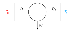
In a Carnot cycle, a system or engine transfers energy in the form of heat between two thermal reservoirs at temperatures and (referred to as the hot and cold reservoirs, respectively), and a part of this transferred energy is converted to the work done by the system. The cycle is reversible is conserved, merely transferred between the thermal reservoirs and the system without gain or loss. When work is applied to the system, heat moves from the cold to hot reservoir (heat pump or refrigeration). When heat moves from the hot to the cold reservoir, the system applies work to the environment. The work done by the system or engine to the environment per Carnot cycle depends on the temperatures of the thermal reservoirs per cycle such as , where is heat transferred from the hot reservoir to the system per cycle.


| External videos | |
|---|---|
Stages
[edit]A Carnot cycle is an idealized thermodynamic cycle performed by a Carnot heat engine, consisting of the following steps:

Isothermal expansion. Heat (as an energy) is transferred reversibly from the hot temperature reservoir at constant temperature TH to the gas at a temperature infinitesimally less than TH. (The infinitesimal temperature difference allows the heat to transfer into the gas without a significant change in the gas temperature. This is called isothermal heat addition or absorption.) During this step (1 to 2 on Figure 1, A to B in Figure 2), the gas is in thermal contact with the hot temperature reservoir, and is thermally isolated from the cold temperature reservoir. The gas is allowed to expand, doing work on the surroundings by pushing up the piston (Stage One figure, right). Although the pressure drops from points 1 to 2 (figure 1) the temperature of the gas does not change during the process because the heat transferred from the hot temperature reservoir to the gas is exactly used to do work on the surroundings by the gas. There is no change in the gas internal energy, and no change in the gas temperature. Heat QH > 0 is absorbed from the hot temperature reservoir. Note: the text in this image incorrectly states "the heat ... is absorbed by the ideal gas particles..." There are no gas particles in the ideal gas model. In the ideal gas model, the gas is a continuum with state variables: Pressure and Temperature. Molecular weight and molecular symmetry are relevant to the molecular theory of gas, not the ideal gas model. Molecules don't absorb or emit heat, and molecules are not part of the ideal gas model. The text should read:"the heat ... is absorbed by the gas as internal energy ..."

(reversible adiabatic) expansion of the gas ( work output). For this step (2 to 3 on Figure 1, B to C in Figure 2) the gas in the engine is thermally insulated from both the hot and cold reservoirs, thus they neither gain nor lose heat. It is an adiabatic process. The gas continues to expand with reduction of its pressure, doing work on the surroundings (raising the piston; Stage Two figure, right), and losing an amount of internal energy equal to the work done. The loss of internal energy causes the gas to cool. In this step it is cooled to a temperature that is infinitesimally higher than the cold reservoir temperature TC. Note: the text in this image incorrectly states "...allows the gas particles to cool..." There are no gas particles in the ideal gas model. The text should read:"...allows the gas to cool..."

Isothermal compression. Heat is transferred reversibly to the low temperature reservoir at a constant temperature TC (isothermal heat rejection). In this step (3 to 4 on Figure 1, C to D on Figure 2), the gas in the engine is in thermal contact with the cold reservoir at temperature TC, and is thermally isolated from the hot reservoir. The gas temperature is infinitesimally higher than TC to allow heat transfer from the gas to the cold reservoir. There is no change in temperature, it is an isothermal process. The surroundings do work on the gas, pushing the piston down (Stage Three figure, right). An amount of energy earned by the gas from this work exactly transfers as a heat energy QC < 0 (negative as leaving from the system, according to the universal convention in thermodynamics) to the cold reservoir.

Compression. (4 to 1 on Figure 1, D to A on Figure 2) Once again the gas in the engine is thermally insulated from the hot and cold reservoirs, and the engine is assumed to be frictionless and the process is slow enough, hence reversible. During this step, the surroundings do work on the gas, pushing the piston down further (Stage Four figure, right), increasing its internal energy, compressing it, and causing its temperature to rise back to the temperature infinitesimally less than TH due solely to the work added to the system. At this point the gas is in the same state as at the start of step 1.


In this case, since it is a reversible thermodynamic cycle (no net change in the system and its surroundings per cycle)[1][2]

This is true as and are both smaller in magnitude and in fact are in the same ratio as .


The pressure–volume graph
[edit]When a Carnot cycle is plotted on a pressure–volume diagram (Figure 1), the isothermal stages follow the isotherm lines for the working fluid, the adiabatic stages move between isotherms, and the area bounded by the complete cycle path represents the total work that can be done during one cycle. From point 1 to 2 and point 3 to 4 the temperature is constant (isothermal process). Heat transfer from point 4 to 1 and point 2 to 3 are equal to zero (adiabatic process).
Properties and significance
[edit]
The Carnot cycle
[edit]
Evaluation of the above integral is particularly simple for a Carnot cycle. Due to energy conservation, the net heat transferred, , is equal to the work performed[2]


The efficiency is defined to be:

| 3 |

where
- W is the work done by the system (energy exiting the system as work),
- > 0 is the heat taken from the system (heat energy leaving the system),
- > 0 is the heat put into the system (heat energy entering the system),
- is the absolute temperature of the cold reservoir, and
- is the absolute temperature of the hot reservoir.
This is the Carnot heat engine working efficiency definition as the fraction of the work done by the system to the thermal energy received by the system from the hot reservoir per cycle. This thermal energy is the cycle initiator.
Reversed Carnot cycle
[edit]A Carnot heat-engine cycle described is a totally reversible cycle. That is, all the processes that compose it can be reversed, in which case it becomes the Carnot heat pump and refrigeration cycle. This time, the cycle remains exactly the same except that the directions of any heat and work interactions are reversed. Heat is absorbed from the low-temperature reservoir, heat is rejected to a high-temperature reservoir, and a work input is required to accomplish all this. The P–V diagram of the reversed Carnot cycle is the same as for the Carnot heat-engine cycle except that the directions of the processes are reversed.[3]
Carnot's theorem
[edit]It can be seen from the above diagram that for any cycle operating between temperatures and , none can exceed the efficiency of a Carnot cycle.
Carnot's theorem is a formal statement of this fact: No engine operating between two heat reservoirs can be more efficient than a Carnot engine operating between those same reservoirs. Thus, Equation 3 gives the maximum efficiency possible for any engine using the corresponding temperatures. A corollary to Carnot's theorem states that: All reversible engines operating between the same heat reservoirs are equally efficient. Rearranging the right side of the equation gives what may be a more easily understood form of the equation, namely that the theoretical maximum efficiency of a heat engine equals the difference in temperature between the hot and cold reservoir divided by the absolute temperature of the hot reservoir. Looking at this formula an interesting fact becomes apparent: Lowering the temperature of the cold reservoir will have more effect on the ceiling efficiency of a heat engine than raising the temperature of the hot reservoir by the same amount. In the real world, this may be difficult to achieve since the cold reservoir is often an existing ambient temperature.
In mesoscopic heat engines, work per cycle of operation in general fluctuates due to thermal noise. If the cycle is performed quasi-statically, the fluctuations vanish even on the mesoscale.[4] However, if the cycle is performed faster than the relaxation time of the working medium, the fluctuations of work are inevitable. Nevertheless, when work and heat fluctuations are counted, an exact equality relates the exponential average of work performed by any heat engine to the heat transfer from the hotter heat bath.[5]
Efficiency of real heat engines
[edit]Carnot realized that, in reality, it is not possible to build a thermodynamically reversible engine. So, real heat engines are even less efficient than indicated by Equation 3. In addition, real engines that operate along the Carnot cycle style (isothermal expansion / adiabatic expansion / isothermal compression / adiabatic compression) are rare. Nevertheless, Equation 3 is extremely useful for determining the maximum efficiency that could ever be expected for a given set of thermal reservoirs.
This can help illustrate, for example, why a reheater or a regenerator can improve the thermal efficiency of steam power plants by increasing the value of and why the thermal efficiency of combined-cycle power plants (which incorporate gas turbines operating at even higher temperatures) exceeds that of conventional steam plants. The first prototype of the diesel engine was based on the principles of the Carnot cycle.
As a macroscopic construct
[edit]The Carnot heat engine is, ultimately, a theoretical construct based on an idealized thermodynamic system. On a practical human-scale level the Carnot cycle has proven a valuable model, as in advancing the development of the diesel engine. However, on a macroscopic scale limitations placed by the model's assumptions prove it impractical, and, ultimately, incapable of doing any work.[6] As such, per Carnot's theorem, the Carnot engine may be thought as the theoretical limit of macroscopic scale heat engines rather than any practical device that could ever be built.[7]
See also
[edit]References
[edit]- Notes
- ^ Fermi, E. (1956). "equation 64". Thermodynamics (PDF). Dover Publications. p. 48.
- ^ a b Planck, M. (1945). "equations 39, 40 and 65 in sections §90 & §137". Treatise on Thermodynamics. Dover Publications. pp. 75, 135.
- ^ Çengel, Yunus A., and Michael A. Boles. Thermodynamics: An Engineering Approach. 7th ed. New York: McGraw-Hill, 2011. p. 299. Print.
- ^ Holubec Viktor and Ryabov Artem (2018). "Cycling Tames Power Fluctuations near Optimum Efficiency". Phys. Rev. Lett. 121 (12): 120601. arXiv:1805.00848. Bibcode:2018PhRvL.121l0601H. doi:10.1103/PhysRevLett.121.120601. PMID 30296120. S2CID 52943273.
- ^ N. A. Sinitsyn (2011). "Fluctuation Relation for Heat Engines". J. Phys. A: Math. Theor. 44 (40): 405001. arXiv:1111.7014. Bibcode:2011JPhA...44N5001S. doi:10.1088/1751-8113/44/40/405001. S2CID 119261929.
- ^ Liu, Hang; Meng, Xin-He (18 August 2017). "Effects of dark energy on the efficiency of charged AdS black holes as heat engines". The European Physical Journal C. 77 (8): 556. arXiv:1704.04363. doi:10.1140/epjc/s10052-017-5134-9. ISSN 1434-6052.
...since the Carnot heat engine, setting an upper bound on the efficiency of a heat engine is an ideal, reversible engine of which a single cycle must be performed in infinite time which is impractical and so the Carnot engine has zero power.
- ^ Benenti, Giuliano; Casati, Giulio; Wang, Jiao (2020). "Power, efficiency, and fluctuations in steady-state heat engines" (PDF). Physical Review E. 102 (4).
However, fluctuations [in reservoir temperature] make impractical such engines.
- Sources
-
- Carnot, Sadi, Reflections on the Motive Power of Fire
- Ewing, J. A. (1910) The Steam-Engine and Other Engines edition 3, page 62, via Internet Archive
- Feynman, Richard P.; Leighton, Robert B.; Sands, Matthew (1963). The Feynman Lectures on Physics. Addison-Wesley Publishing Company. pp. Chapter 44. ISBN 978-0-201-02116-5.
{{cite book}}: ISBN / Date incompatibility (help) - Halliday, David; Resnick, Robert (1978). Physics (3rd ed.). John Wiley & Sons. pp. 541–548. ISBN 978-0-471-02456-9.
- Kittel, Charles; Kroemer, Herbert (1980). Thermal Physics (2nd ed.). W. H. Freeman Company. ISBN 978-0-7167-1088-2.
- Kostic, M (2011). "Revisiting The Second Law of Energy Degradation and Entropy Generation: From Sadi Carnot's Ingenious Reasoning to Holistic Generalization". AIP Conf. Proc. AIP Conference Proceedings. 1411 (1): 327–350. Bibcode:2011AIPC.1411..327K. CiteSeerX 10.1.1.405.1945. doi:10.1063/1.3665247. American Institute of Physics, 2011. ISBN 978-0-7354-0985-9. Abstract at: [1]. Full article (24 pages [2]), also at [3].
External links
[edit]- Hyperphysics article on the Carnot cycle.
- S. M. Blinder Carnot Cycle on Ideal Gas powered by Wolfram Mathematica
| Authority control databases: National |
|---|